Comparing with floor heating, the fan coil system is essentially a completely watery system. Fan Coil Unit includes a fan and a coil which are used for heating and cooling and these units need a thermostat to be controlled.
If there is a single coil in the fan coil used, the system is called 2 pipes fan coil system. Two pipes circulate in the system making distribution and collection. A distribution pipe and a collection pipe are connected to each fan coil unit. In this case, either cold water or hot water can be circulated throughout the system.
If there are two separate pipes as heating and cooling in the fan coil, the installed system is called a four-pipe fan coil system. Four pipes circulate in the system, making two distributions and two collecting. Two distribution pipes and two collector pipes are connected to each fan coil unit. Cold water circulates independently in one of the pipe pairs and hot water in the other. Therefore, heating and cooling can be done simultaneously in each fan coil unit independently of each other. Compared to the 2 pipes, the 4 pipes are more complex but easier for the water management.Since fan coil systems operate in heating and cooling, it is required to perform heating or cooling in summer or winter periods. In this case, we will normally introduce the change-over sensor which is used to detect water temperature (to judge winter or summer). In General situation, heating or cooling mode selection can be made manually. When heating mode selected; If the room temperature falls below the set temperature, the fan coil is activated and tries to heat the environment. In cooling mode, if the room temperature rises above the set temperature, the fan coil is activated and tries to cool the environment.Where are the fan coil thermostats installed?Fan coil systems used in commercial buildings such as hospitals, hotels, shopping malls and business centers operate in two types. These systems, called 2-pipe and 4-pipe, directly affect the comfort and energy savings of the users.Based on different applications, Modbus/Bacnet/KNX protocol based fan coil thermostat is needed for different installations.
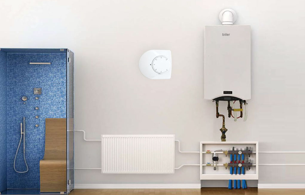
This room thermostat is only used in heating systems to maintain the selected room temperature. If the room temperature falls below the selected setpoint, the heating contact will open. If the room temperature exceeds the selected setpoint, the heating contact will close.
Temperature control is based on internal sensor. An external sensor (SENSOR 10K ) can be connected without any additional external power supply.
Compatibles with both NC and NO actuators, such as Gas boiler or oil buners
Mounting, Installation and Commissioning
The room thermostat should be located where the air temperature can be sensed as accurately as possible, without getting adversely affected by direct solar radiation or other heat or refrigeration sources. Mounting height is about 1.5 m above the floor.
The unit can be fitted to most commercially available recessed conduit boxes or directly on the wall. Only authorized personnel may open the unit to perform service. The unit must be isolated from the mains supply before opening. When installing the unit, first remove the cover of room thermostat, and then fix the thermostat body to wall. Then make the calibration as below. Use a sensible thermometer with this thermostat, in some atmosphere and be sure about the real temperature of room. Then remove plastic round cover of set point.
For example, the room temperature is 20 °C indicated on sensible thermometer. You must turn set point till you hear click voice. Then put the set point cover by matching 20 °C with arrow on cover of room thermostat. The thermostat must be mounted on a flat wall. The local electrical regulations must be complied with. If there are thermostatic radiator valves in the reference room, set them to their fully open position. The diaphragm is filled with environmentally friendly gas. The thermostat housing is made of plastic.
There are two main options when considering KNX thermostats.
Display&Control with integrated temperature sensor and regulation. This will output a signal based on the defined set point and temperature. The control may have a display to change the set point or alternatively this will need to be set from a separate user interface
Thermostat with integrated temperature sensor only. This will need to be sent to a separate regulator, which will then output the demand signal. With no display a user interface will need to be provided elsewhere on the system.
The location of the thermostat can affect the operation of the system, however as this is generally outside of the integrators control it is possible to counter this by:
Calibration - All KNX temperature sensors have the ability to offset the temperature. Once an accurate temperature from the room is received, the sensor value can be calibrated.
External temperature sensor - This allows a temperature from the bus to be used to either average a room temperature or replace it. As most KNX switches now have a built in temperature sensor, you can read the temperature at each end of the room creating a more representative reading.
The majority of KNX heating regulators support 4 stages of heating and cooling:
– Heating Basic
– Sub Heating
– Cooling Basic
– Sub Cooling
Each stage has a separate output and defined thresholds for use.
If the temperature falls below the set point, less the additional band (20-2=18) then the radiators will be used until the temperature rises. In this way the room temperature will be constantly maintained in the most comfortable way possible.
There are various devices the can be used for external regulators including - manifold controls, logic modules, input devices and servers. In each case it is important to confirm the functionality as some are limited to only 2 stage i.e heating and cooling with no additional stages.